Three 5G test challenges to overcome
Article By : Adnan Khan, Anritsu

Changing standards, mmWaves, and cost of test will impact your designs.
The early 2017 announcement by 3GPP that the first version of 5G new radio (NR) standards will be published around December 2017 came as a welcome sign to engineers at chipset and device developers, as well as carriers. Test companies will also benefit from having a better map to follow as the industry continues down the path to 5G.
A key benefit of the standard is that it will provide a fundamental understanding of the architecture that will be used in the initial rollout of the next wireless technology. It is expected that there will be some convergence in certain elements, such as in bandwidth and Multiple Input, Multiple Output (MIMO) combinations. The industry now also knows that the first application will be enhanced mobile broadband. Other aspects, such as massive IoT, ultra-reliability, and mission critical, will be rolled out at later dates.
While the foundation of 5G is being solidified, many questions remain. For engineers who are developing systems for the next generation of wireless networks, this poses many challenges, including how to verify their designs. Among the most difficult obstacles are the evolution of the standard, millimeter wave (mmWave) adoption, and controlling the cost of test.
Standards evolution
Even though the first version of the standards will be released by year’s end, 5G remains a bit of unchartered territory. When the industry moved from 3G to 4G, the transition was made smoother by similarities such as frequency coverage, propagation and many other parameters. That is not entirely the case with 5G. While LTE technology will be leveraged in many 5G applications, mmWave frequencies will be used to accommodate the high-bandwidth services expected with the rollout. It’s interesting to note that between 28 GHz, 37 GHz, and 39 GHz, there is 3.85 GHz of bandwidth available—six times the amount of spectrum the FCC has ever authorized.
The initial specification outlined in the December 2017 3GPP standard will focus on the non-standalone (NSA) mode. NSA will utilize existing LTE radio and the evolved packet core network as an anchor for mobility management and coverage. It will also add a new radio access carrier to enable certain use cases, namely fixed-wireless broadband.
Early 5G deployment will have dual connectivity that will enable the networks to provide multi-standard and multi-band support in both devices and radio access. Core mobile device actions, such as scheduling and handovers, will be conducted using the LTE channel to leverage its broader coverage. mmWave will serve as the data pipe, as it provides much faster throughput for high-bandwidth services.
A second 5G mode is standalone (SA). This version, as the name implies, can be deployed in greenfield situations and won’t rely on existing LTE elements. The first version of the 3GPP specification is not expected to address SA, leaving engineers to speculate on the conditions of this mode. Further complicating matters is that there will undoubtedly be revisions made to the NSA specifications over the next few years.
Engineers are left with no firm guideline to develop products. To address this issue, test manufacturers must collaborate with chipset vendors and carriers to develop common assumptions about 5G and advocate that they be included in the standards. Coupling these discussions with participation in the 3GPP standards development meetings has resulted in a consensus of what the specifications will likely be in the short-term and long-term. Based on all this information, guidelines have been established to help test vendors develop solutions that allow engineers to develop accurate models that can help expedite the design process.
mmWave challenges
Even though LTE will be an integral part of 5G, mmWave will have a strong role because of its throughput advantages. Aggregated Channel bandwidth in mmWave bands is expected to be 1 GHz and higher, significantly wider than the 20 MHz offered by LTE.
There are some tradeoffs associated with the ability to transmit considerably more data. High frequency results in shorter wavelengths. In the case of mmWave, the range is 1 mm to 10 mm. Signal power can also be easily diminished due to the higher frequencies’ vulnerability to gases, rain, humidity absorption, and foliage. As a result, mmWave can only transmit for short distances and will need Line of sight (LoS) propagation.
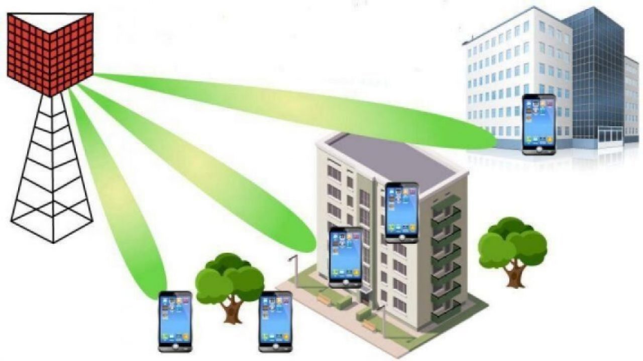
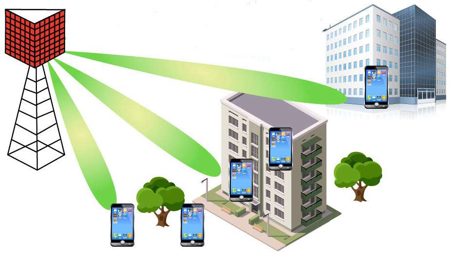
To compensate for limited transmission distance and operation in Non-Line of Sight (NLoS) environments, smart beamforming and beam tracking will be integrated into 5G transmissions. Beamforming, as shown in Figure 1, is a traffic-signaling system that identifies the most efficient data-delivery route to a user, as well as reduces interference for those nearby in the process. Beamforming is an effective technique in helping massive MIMO arrays make more efficient use of nearby spectrum.

Figure 1 Beamforming transmits data to specific devices.
Beamforming and other mmWave applications create test challenges, as engineers must conduct static tests on devices and antennas in active beam forming environments. Engineers must find how many points are necessary to obtain an accurate measurement, but not too many that tests are inefficient and costly.
One of the most important tests on mmWave devices is propagation loss. As previously stated, signal power at high frequencies can be diminished by environmental conditions. At 28 GHz, loss is approximately 40 dB higher than at LTE frequencies. This is considerable when you account for the fact that total power is reduced by half for every 3 dB of loss.
Propagation loss issues are compounded by 5G mobile device designs. Currently, engineers verify transceiver performance by conducting a series of tests, such as EVM, occupied bandwidth, spectral emission mask, leakage, and adjacent channel power leakage ratio (ACLR). To test antennas, which are integrated on the board or within the housing, Over-the-Air (OTA) measurements, including power and sensitivity, are employed. OTA tests are also conducted to ensure the mobile device performs according to specification in a real-world environment.
Testing is different as it relates to the next generation of mobile devices. While current mobile terminals have several built-in antennas, those for 5G will have significantly higher antenna counts. Additionally, antenna arrays are embedded in the chip of a 5G mobile device, making it significantly more challenging for engineers to verify their performance. Implementing a measurement connector for each antenna would cause problems with mobile-terminal size and contradict cost reduction trends.
Conducting OTA tests on mmWave designs has a cost detriment. Traditionally, two test chambers—the reverberation chamber and the more-expensive anechoic chamber—are used when performing OTA measurements. Studies indicate that better results are achieved by conducting far-field measurements (FFM) on mmWave designs. Using this as a basis, OTA measurements will have to be taken 1.5 m to 2 m on devices supporting 28 GHz. That will require a significant investment, as the test chambers would be considerably larger than those currently used for LTE.
Cost of test
Controlling costs will play a key role in the success of 5G. If there isn’t a compelling business case to deploy 5G services, the technology may not roll out as expected. To control test costs, engineers must make the decision as to which tests need to be done in an OTA chamber. Chipset, device, and carriers all must agree on an acceptable margin of error for certain performance parameters to eliminate the need for some OTA tests. For example, there will be a considerable amount of protocol tests that will need to be performed. Because verifying the protocol stack does not require RF measurements, protocol testing may be done without a chamber.
A second method may be developing FFM conversations or reflection parameters. Using this approach, engineers can conduct near-field measurements (NFM) and use industry-accepted techniques to convert them to an FFM. Table 1 compares FFM and NFM.
| Parameter | NFM | FFM |
| Measurement location | Simple radio anechoic box | Radio anechoic chamber |
| Measurement range | Near Field: About 3λ (ex. 15 to 25 mm @ 60 GHz) | Far Field: (ex. 3 m or 10 m) |
| Radiation Pattern Measurement | 3D | 2D (3D radiation pattern measurement requires time and facilities) |
| Antenna Diagnostics and Analysis | Yes | Difficult |
In an NFM application, compact mmWave measuring instruments can be used and the radiation pattern can be measured using a simple radio anechoic box in a room. This approach eliminates the high cost and long configuration time associated with a measurement system using a large radio anechoic chamber.
In a broader test sense, maintaining economic efficiencies can be achieved through design of the test solutions. Robust, integrated platforms whereby capabilities can be efficiently added as needs expand will allow for a greater ROI on the test investment. It will also simplify adding test cases that address new versions of the standard, which will continue to evolve well past December 2017, as will 5G.
Adnan Khan is Senior Business Development Manager at Anritsu.
Related articles:
- 5G Front haul, backhaul architectures present wireline test challenges
- 5G book gets into the technology details
- What is 5G NR?
- 3GPP Moves 5G Forward in Dubrovnik
- Test is a key challenge for 5G
- Five technologies for building 5G
- OTA testing to gain importance with 5G
- Optimize RF PA efficiency to increase your handset’s talk-time
Subscribe to Newsletter
Test Qr code text s ss


