Calculating a resistor-capacitor snubber
Article By : John Betten

Often adding a simple resistor-capacitor snubber to damp out the ringing is all that is required to tame the circuit. But all too often guess work is used when selecting values.
Most power supply designers have come across ringing in switch-mode converters. This ringing can generate radiated and conducted noise, cause circuit jitter, over-stress components, and create excessive dissipation. This is often a major concern in applications such as audio, processor power, and any design that requires electromagnetic interference (EMI) qualification.
Often adding a simple resistor-capacitor (R-C) snubber to damp out the ringing is all that is required to tame the circuit. But all too often guess work is used when selecting values, resulting in less than optimal performance. Would it not be better if this trial-and-error approach could be replaced with a simple step-by-step process?
![[flyback converter]](/wp-content/uploads/sites/2/2020/04/1.jpg)
Figure 1: *Two common locations in a flyback converter where excessive ringing occurs. In both places, the component lead, PCB, and transformer leakage inductance ring with non-linear component and inter-winding transformer capacitances.
*
Two common locations in a flyback converter where excessive ringing occurs. In both places, the component lead, PCB, and transformer leakage inductance ring with non-linear component and inter-winding transformer capacitances.
The L-C tank rings at a frequency and amplitude that is generally unknown until the circuit is tested. In many instances the ring amplitude and duration is significant and must be reduced. One solution is to damp or "snub" the oscillation with a series R-C circuit, typically placed across the rectifier or the FET.
The seven-step procedure below uses a common methodology that shifts the resonant frequency of the ringing to calculate the circuit's parasitic inductance (L) and capacitance (Co). Once these are known, the snubber capacitor (Csnub) and resistor (Rsnub) are calculated, which provide a reasonable starting set of values for the R-C snubber. The example waveforms in the images below were taken with an R-C snubber placed in parallel with the rectifier.
![[Un-snubbed rectifier ringing-frequency-shifted ringing ]](/wp-content/uploads/sites/2/2020/04/2.jpg)
__Figure 2:__ *Un-snubbed rectifier ringing (top) and frequency-shifted ringing (bottom).*
The following are seven steps you can use to calculate a snubber.
![[7 steps to calculate a snubber]](/wp-content/uploads/sites/2/2020/04/3.jpg)
![[Snubber resistor value ]](/wp-content/uploads/sites/2/2020/04/4.jpg)
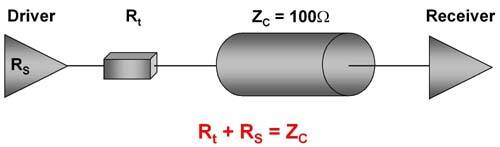
__Figure 3: __ A snubber resistor value equal to the circuit's characteristic impedance minimises ringing, but at maximum power loss.
Undamped ringing in switching converters can create excessive EMI and overstress components. An R-C snubber that is properly calculated can be instrumental in taming these issues. The seven-step procedure detailed above is simple to follow and provides a good starting point to help the designer "damp the ringing."
About the author
John Betten is an Applications Engineer at Texas Instruments.

Subscribe to Newsletter
Test Qr code text s ss